


The Shift to Single-Use Systems in Pharmaceutical Manufacturing
Driven by the rapid advancement of biologics in modern medicine, single-use systems (SUS) are shifting pharmaceutical manufacturing from rigid, large-scale, stainless-steel facilities to agile, closed systems. By replacing reusable equipment with pre-sterilized disposables (e.g., bioreactor bags, tubing, and filters), manufacturers eliminate time-consuming cleaning and sterilization, allowing for faster batch turnarounds. Facilities can quickly switch between different biologic drug products (e.g., monoclonal antibodies, vaccines, gene therapies, and recombinant proteins), significantly increasing overall manufacturing capacity and flexibility. Further, by using fresh, sterile components for every batch, the risk of carryover between runs is greatly reduced, not only improving efficiency and speed, but most importantly, safety.
Ensuring the quality of single-use technologies (SUT) requires stringent control over particulate contaminants on the surfaces of the components that touch the drug product. Particulates in bioreactors can compromise cell viability, interfere with media nutrients, and elevate bioburden risks, potentially ruining the entire batch through microbial contamination. Because SUT are designed to be used only once before being discarded, cleanliness qualification must be assured by suppliers before end-user implementation.
ASTM International recently published standard ASTM E3230-20 (Standard Practice for Extraction of Particulate Matter from the Surfaces of Single-Use Components and Assemblies Designed for Use in Biopharmaceutical Manufacturing) to address critical industry challenges related to patient safety risks, regulatory gaps, supply chain trust, and the need for realistic best practice expectations for manufacturers. Prior to E3230-20, SUT suppliers and end-users struggled to agree on particle limits because no standardized extraction method existed. The standard now provides a globally recognized benchmark to ensure supplier cleanliness claims can be measured against existing pharmacopeial standards (like USP <788>).
While ASTM E3230-20 focuses on the extraction process—how to flush, rinse, or agitate SUT to get particles off the surface and into a liquid solution—it does not dictate a single analysis method. Instead, it relies on companion guides like ASTM E3060-23 (Standard Guide for Subvisible Particle Measurement in Biopharmaceutical Manufacturing Using Dynamic (Flow) Imaging Microscopy) that specifically references the USP chapters related to particulate matter, including USP <787> (Subvisible Particulate Matter in Therapeutic Protein Injections), USP <788> (Particulate Matter in Injections), and USP <1788> (Methods for Determination of Particulate Matter in Injections and Ophthalmic Solutions), to evaluate the particulate content of the extraction fluid.
As an already established orthogonal USP analytical tool (USP <788>, USP <787>, USP <1788>, and USP <790>), flow imaging microscopy is well-suited to reliably detect, quantify, and characterize the unique types of particulate matter in SUS extractions.
Why Imaging is Key to Quality Control and Particle Source Identification in Single-Use Technologies
SUT are manufactured from a range of polymeric materials that can shed particulates during production, handling, and storage. Due to their inherently low electrical conductivity, polymeric materials are inefficient at dissipating electrostatic charge. This characteristic promotes charge buildup on surfaces, enhancing the attraction of fine, oppositely charged particulates and increasing the risk of contamination.
The geometric shape, surface texture, and edge profiles of abraded microplastics—microscopic polymeric shards, flakes, or fibers—act like a physical forensic blueprint, allowing quality engineers to map particles back to the specific mechanical force that created them. Because different SUT fabrication steps use distinct forces (shearing, tearing, friction, or compression), each process imprints a unique morphological signature on the resulting debris.
Flow Imaging Microscopy with FlowCam: Large-Scale Data from Real Images
Flow imaging microscopy (FIM) calculates a wide range of morphological parameters in real time, including shape, size, aspect ratio, and transparency, revealing these morphologies as a rich dataset that supports direct linkage of particles to their source.
Because FIM with FlowCam is an image-based technique, particle property measurements are derived directly from high-resolution digital images without relying on mathematical assumptions that include spherical bias. Measurements—such as area-based diameter (ABD), transparency, intensity, roughness, maximum Feret diameter (fiber length), and geodesic length—are automatically extracted by FlowCam’s advanced software, transforming qualitative visual observations into quantifiable morphological data that enables more reliable particle classification and robust quality monitoring of SUS extraction fluid.
Beyond size and shape metrics, FIM analyzes how particles interact with light by calculating the gray-scale pixel values within detected particle boundaries. Measuring intensity and transparency values is critical for differentiating particles that share similar dimensions but consist of entirely different materials. Light interaction analysis allows FIM to distinguish and classify even the most highly translucent SUT particulate contaminants, which often remain undetected by traditional methods.
Using FlowCam Images for Root Cause Determination in Single-Use Systems
Because every detected particle is imaged, analysts can rapidly distinguish between particle classes: metallic debris (dense, opaque), microplastics (translucent, sheet-like), fibers (elongated, low aspect ratio), and biological contaminants such as bacterial cells or pollen. This morphological fingerprinting accelerates root-cause investigation and enables targeted corrective action, whether the contamination source is a component supplier, an assembly step, or the bioprocess itself.
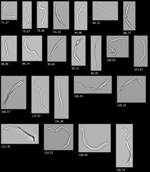
For instance, particles that resemble long, uniform spirals, curled shavings, or ribbon-like strips (pictured below) might indicate a malfunction of mechanical cutting tools used to slice SUT tubing. If the particle edges are jagged or multi-layered, it could mean the cutting blade is dull and needs replacement.

Similarly, irregular, crescent-shaped flakes or slivers (pictured below) could point to manual assembly lines where workers force rigid barbed connectors into flexible tubing.

In contrast, flat, irregular flakes with smooth, glassy surfaces and micro-fractured, cracked borders (pictured below) may have originated from heat-welding and sealing dies used to fabricate the perimeter of SUT bags. The smooth face may indicate that the plastic was melted against a polished metal die. However, if the seal was overheated or the die retracted too quickly, the border of the weld can become brittle and fracture into flat, glass-like fragments of clear plastic debris under the mechanical stress of folding and packaging the SUT bags.

Another distinct pattern includes rounded grains, smooth-edged granules, or fine dust particles, which might indicate vibratory feed bowls, guide rails, or shipping transit abrasion. High-velocity friction creates sharp particles, whereas low-energy, continuous friction (like plastic parts tumbling together or rubbing against packaging during shipping) acts like a rock tumbler. It continuously grinds down sharp edges, leaving behind dull, rounded micro-granules.

Finally, thin, feather-like films or irregular webs with highly variable frayed, stringy edges may suggest the injection molding process of connectors or ports, or that the manual trimming of excess plastic is the source. When liquid plastic seeps between mold halves, it creates ultra-thin “flashing”. If this flashing is not cleanly removed, or if it is manually scraped off with a razor, it sheds feather-light, thin films into the component.

Particulate Monitoring Across Single-Use System Workflows
Effective particulate control in SUS-based bioprocessing requires monitoring at multiple points, not just at final product release. FlowCam supports a monitoring strategy across the full SUT lifecycle:
- Supplier qualification and incoming inspection: ASTM E3230-20 provides a standardized extraction protocol for SUT component surfaces. FlowCam analysis of the resulting extraction fluids delivers objective, image-based cleanliness evidence (benchmarked against ISO 16232, IEST-STD-CC1246, or internal specifications) before assemblies ever enter service.
- In-process wash fluid monitoring: FlowCam analysis of aqueous rinse and flush fluids provides a direct readout of what was removed from SUT components. Configurable size bin filters enable automated, documentable pass/fail determinations against regulatory or internal cleanliness specifications.
ASTM Regulatory Alignment and Data Integrity
ASTM E3060-23, the standard test method for measurement of subvisible particulate matter in biopharmaceutical products using flow imaging microscopy, provides a rigorous procedural framework for FlowCam analysis in regulated environments. Together with ASTM E3230-20, these standards give SUT manufacturers and their biopharma customers a clear, reliable analytical pathway for particulate characterization across the product lifecycle.
VisualSpreadsheet, the software platform that accompanies FlowCam instruments, supports 21 CFR Part 11-compliant data management, audit trail functionality, and customizable reporting—enabling seamless integration into existing quality systems.
From Data to Decision: A Faster Path to Contamination Control
The practical advantage of image-based particulate monitoring becomes clearest when something goes wrong. When a particle count excursion occurs in a wash fluid, an extraction sample, or a bioreactor bag qualification run, the question that follows immediately is: Where are the excessive particles coming from?
With traditional counting methods, answering that question requires a lot of additional investigation—often manual microscopy, additional sampling, or time-consuming root-cause analysis. With FlowCam, the particle images are already in hand. An analyst can review the morphology of the flagged population within minutes, distinguish between fiber contamination from a packaging material, opaque debris from a metal fitting, or translucent flakes from a polymeric component, and direct the investigation accordingly.
For biopharma manufacturers operating under intense pressure to maintain batch schedules while meeting quality standards, that speed matters. Faster identification of contamination sources means faster corrective action, fewer lost batches, and a more robust quality system overall.
From USP <788> to ASTM E3230-20: Complete Particulate Characterization of Single-Use Systems with Flow Imaging Microscopy
SUS have transformed biopharmaceutical manufacturing, and with that transformation has come a corresponding need for analytical tools capable of meeting the cleanliness qualification demands of modern bioprocessing. FIM with FlowCam provides the particle count data required for regulatory compliance, combined with the morphological information needed to understand what those particles are and where they came from.
Whether you are an SUT component supplier conducting incoming cleanliness qualification, a contract manufacturer validating wash processes, or a biopharmaceutical manufacturer qualifying bioreactor assemblies for GMP production, FlowCam offers a direct imaging approach that goes beyond counting—giving your quality team the data they need to act with confidence.
Ready to learn more about how FlowCam fits into your SUS particle monitoring workflow?